
2.2Modbus devices and datapoints
Configure Modbus devices on the gateway's RS485 or RS232 port or over the network (Modbus TCP), define datapoints, and test registers.
This is the installer reference for Modbus in Veltnova. It explains how Modbus RTU works, how to set up the serial port, devices and datapoints in the Configurator, how to use the values, and how to commission and troubleshoot a bus.
#1. Fundamentals
#Master and slaves
Modbus RTU is a serial protocol with one master and up to 247 slaves on the same bus. The master starts every exchange: it sends a request to one slave, and only that slave answers. Slaves never speak on their own, and a second master on the same bus causes collisions.
The Veltnova gateway is always the master. For each datapoint it sends one request, waits for the reply, checks the CRC (the error check at the end of every frame) and decodes the answer. Each slave is identified by its Slave ID (1 to 247), set on the device itself. Every device on one bus needs a different Slave ID. The gateway has two independent serial buses, RS485 and RS232, each with its own master and device list, so an ID only has to be unique within one bus.
#Data areas and function codes
A device exposes its data in four areas. The same address number can exist in more than one area, so you always have to say which area you mean. In the Configurator you choose it with the Read function.
| Area | Item size | Read function | Write function | Typical content |
|---|---|---|---|---|
| Coils | 1 bit | 01 | 05 (one), 0F (many) | Outputs, on/off commands |
| Discrete inputs | 1 bit | 02 | none (read only) | Digital inputs, alarm flags |
| Holding registers | 16 bit | 03 | 06 (one), 10 (many) | Settings, setpoints, often measurements too |
| Input registers | 16 bit | 04 | none (read only) | Measurements, status words |
#Registers and multi-register values
A register holds 16 bits, sent high byte first. A 16-bit value fits in one register. A 32-bit integer or float needs two consecutive registers, and text uses two characters per register. Some devices pack several flags into one status register; you read one flag with Bit number, where bit 0 is the least significant bit.
#Byte and word order
Modbus does not say which register of a 32-bit value comes first, so manufacturers differ. The four options are named after the four bytes of the number, A (most significant) to D (least significant). The table shows how the number 100000 (0x000186A0) arrives in the two registers for each setting.
| Word order | First register | Second register | Notes |
|---|---|---|---|
| ABCD (normal) | 0x0001 | 0x86A0 | High word first. The default. |
| CDAB (word swap) | 0x86A0 | 0x0001 | Low word first. Very common. |
| BADC (byte swap) | 0x0100 | 0xA086 | Bytes swapped inside each register. |
| DCBA (both) | 0xA086 | 0x0100 | Fully reversed. |
If a 32-bit or float value reads as nonsense, change the word order first. It affects 32-bit integers and floats only.
#Addressing: protocol address, 1-based numbers and hex
On the wire a register has a protocol address from 0 to 65535, counted from zero. Manuals often print something else: zero-based addresses (often in hex), Modicon numbers (4xxxx holding registers, 3xxxx input registers, 1xxxx discrete inputs, 0xxxx coils, with six-digit variants such as 400001), or plain 1-based register numbers.
What this Configurator expects. The Data address field takes the zero-based protocol address. The gateway sends exactly the number you type, with no offset. Hexadecimal needs a 0x prefix (0x2000); decimal needs none (8192). Spaces are ignored and the value is limited to 0 to 65535. Hex digits without the prefix are read as decimal when they are all digits (0100 is 100) and otherwise, like 2000h or 1A, silently become address 0, so read the address back after typing it.
The area comes from the Read function, so never type the area prefix. Convert like this:
| The manual says | Meaning | Read function | Type in Data address |
|---|---|---|---|
Address 0x0100 or 256 | Already a protocol address | As documented | 0x0100 or 256 |
40001 | Holding register, Modicon (subtract 40001) | 03 | 0 |
40108 | Holding register, Modicon | 03 | 107 or 0x006B |
30013 | Input register, Modicon (subtract 30001) | 04 | 12 or 0x000C |
00017 | Coil, Modicon (subtract 1) | 01 | 16 |
Register 100 in a plain 1-based list | Subtract 1 | As documented | 99 or 0x0063 |
Some device families, SunSpec inverters for example, number registers 1-based but with real addresses in the 40000 range. The register documented as 40005 is then at protocol address 40004 (0x9C44): subtract one, not 40001. The built-in Fronius profile is converted this way. When in doubt, test with the Modbus Register Test (section 10) against a value you can see on the device. An off-by-one error usually returns the neighbouring register, not an error.
#2. What you need before you start
- The register map from the device manual: address, area (holding or input), data type, scaling and unit for each value.
- Whether the manual's addresses are zero-based, 1-based or Modicon.
- The device's Slave ID and serial settings (baud rate, data bits, parity, stop bits), and for 32-bit values its word order, if the manual gives it.
- RS485 wiring: a two-wire bus, A to A and B to B on all devices, run as a daisy chain and not a star. Vendors label A and B differently, so a silent device is often swapped. Connect the ground reference where the manual asks for it.
- Termination: a terminating resistor, normally 120 ohm, at each of the two physical ends of the bus. A short bench setup often works without; a long run needs it.
- RS232 is point-to-point, so one device per port. Use RS485 for several devices.
- A deployed gateway with its address and deploy token set in the Configurator, for the Diagnostics tests. See Deploying to a gateway.
#3. Serial port settings
Each bus has its own system object page: RS485 Interface and RS232 Interface. In the right-hand panel open the Server tab, then Interfaces, then the interface.
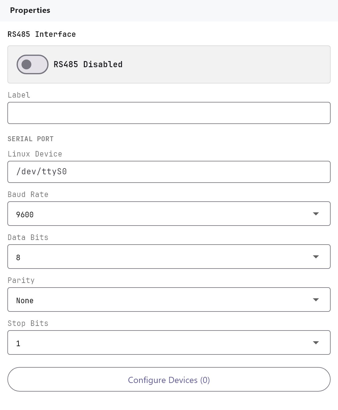
| Field | Notes |
|---|---|
| Enabled | Turns the bus on. With it off nothing on this bus is polled. |
| Label | A display name. |
| Linux device | The port's device path on the gateway. Defaults: /dev/ttyS0 for RS485 and /dev/ttyS3 for RS232. Keep them unless your gateway hardware documentation says otherwise. |
| Baud rate | 2400, 9600 (default), 19200, 38400, 57600, 115200 or 1500000. |
| Data bits | 7 or 8 (default 8). |
| Parity | None (default), Even or Odd. |
| Stop bits | 1 (default) or 2. |
| Modbus RTU devices | Configure RTU Devices (N) opens the device dialog. |
The gateway applies these settings to the port, with no flow control, when you deploy. They must match every device on the bus. Many devices use 9600 baud, 8 data bits, no parity and 1 stop bit, but check the manual: a mismatch is the most common reason for a silent device.
#4. Devices
Click Configure RTU Devices (N) to open the Modbus RTU Devices dialog. With no device yet it offers Add first RTU device.
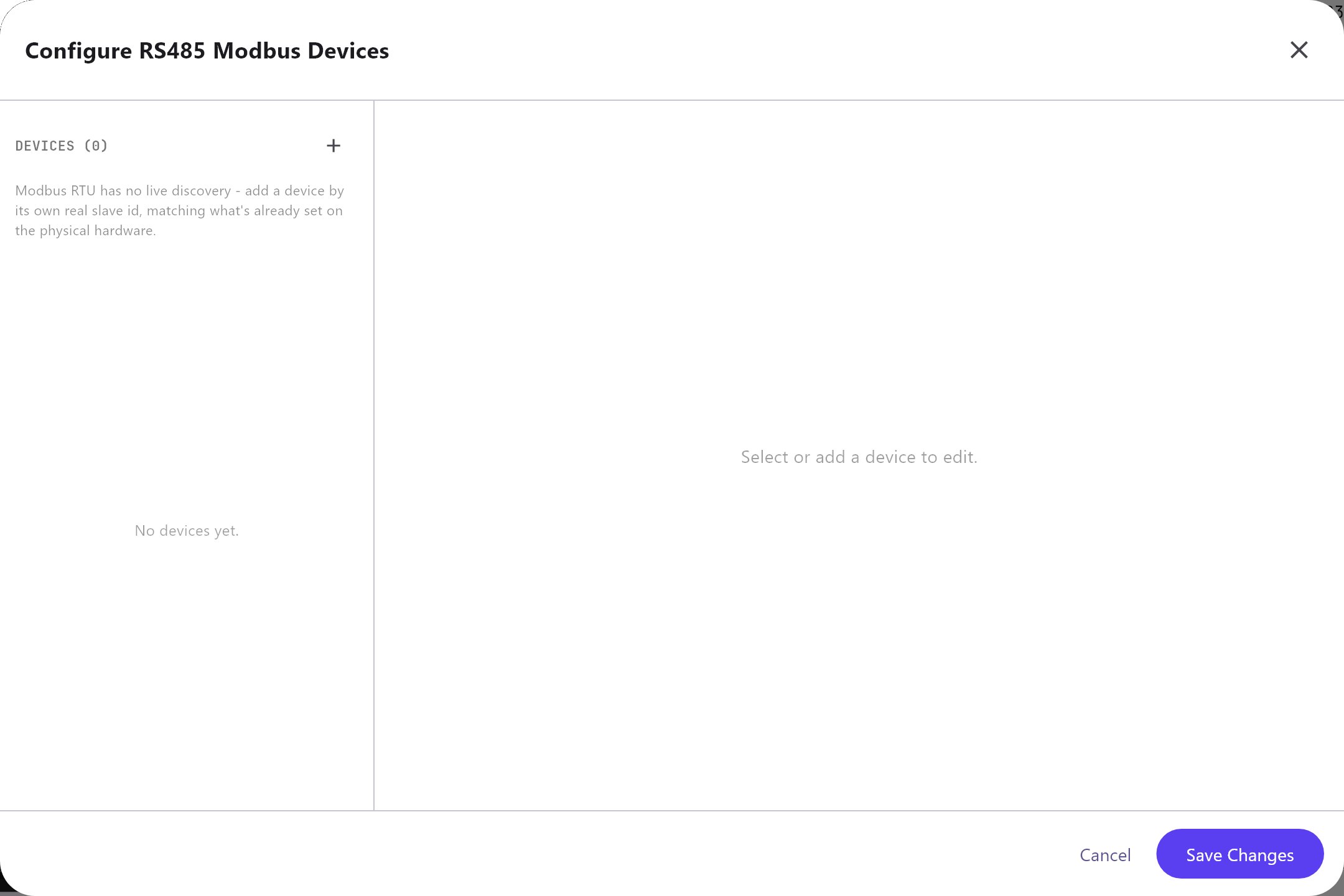
The list on the left shows number, name and Slave ID, with the driver below. Under the list:
- Add creates a device from the Generic Modbus RTU profile, with the next free number as Slave ID (device count plus one), one starter datapoint and one starter command.
- Clone copies the selected device with its datapoints and commands, adds "Copy" to the name ("Copy 2" and so on if that name is taken) and keeps the Slave ID. The copy gets its own Reusable value ID and Reusable command ID from its new name, so it never writes to the original's values.
- Remove deletes the selected device with everything in it.
Edits are written into the project as you make them, so Save Changes and Cancel both just close the dialog. Save the project and deploy as usual.
#Device
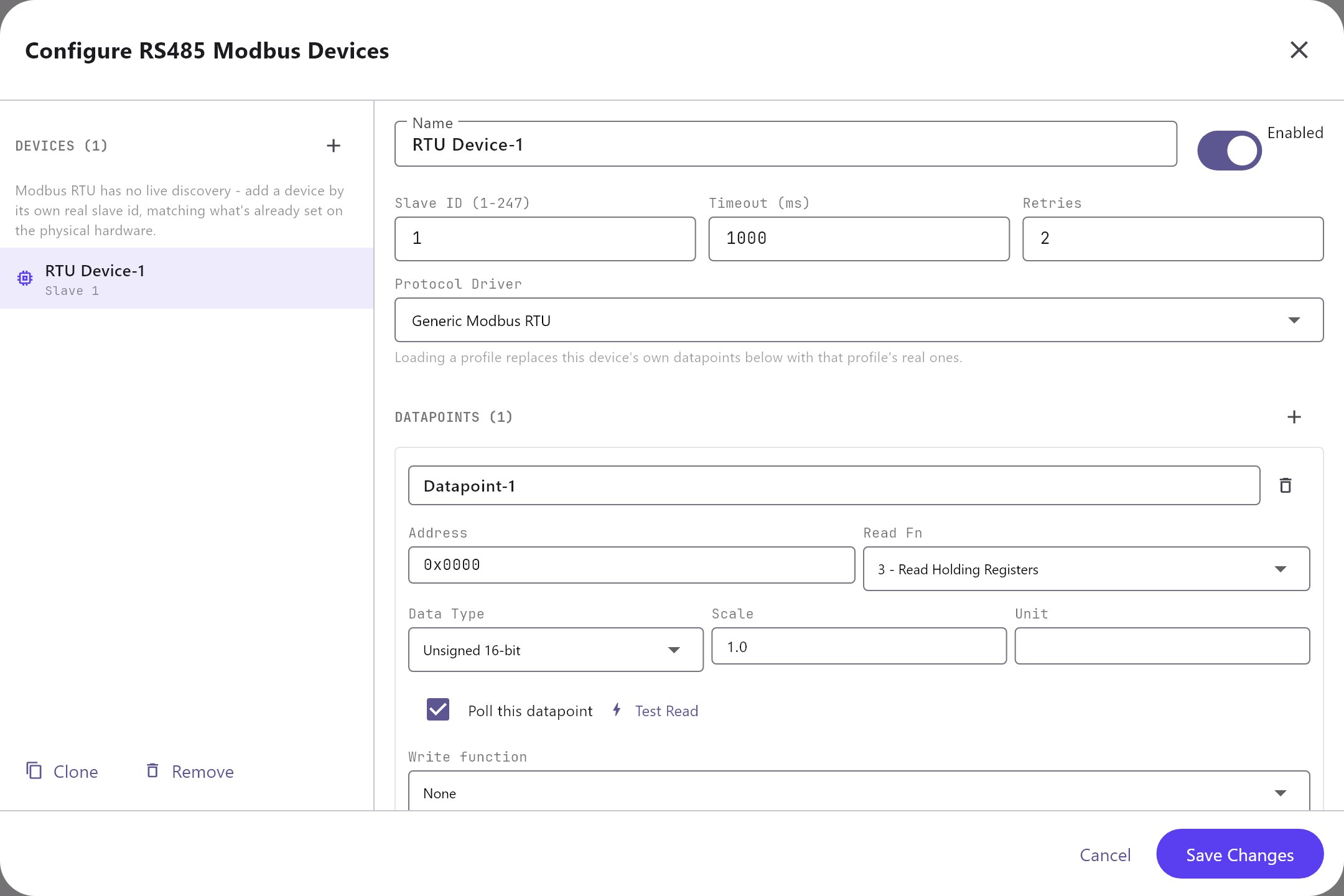
| Field | Notes |
|---|---|
| Protocol driver | A built-in profile for a known device, or Generic Modbus RTU for a free-form one. A profile fills in datapoints and commands (section 7). Load applies the selected profile again. Custom / add new driver just keeps what you enter by hand. |
| Name | A readable name, also used to build the generated IDs. |
| Slave ID | 1 to 247, as set on the device. |
| Enabled | When off, none of the device's datapoints is polled. Switch off a device that is not connected, because every request to it waits for the full timeout. |
| Timeout (ms) | How long the gateway waits for a reply: 100 to 30000, default 1000. The gateway never waits less than 200 ms. |
| Retries | 0 to 10, default 2. Extra attempts after a timeout or a lost connection. Used for Modbus TCP devices and for serial devices, when reading and when writing. A read that times out is tried again right away, so a meter that now and then ignores a request no longer causes an error or an old value on the screens. A serial device that has not answered for the last minute (probably switched off) gets one attempt only, so it cannot slow down the other devices on the same bus. A Modbus exception answer is final and is not retried. |
Replacing datapoints. Choosing a profile in the Protocol driver list on a device that holds more than the starter datapoint and command asks Replace existing datapoints? Replace datapoints swaps in the profile defaults; Keep existing only changes the profile label. The Load button replaces straight away without asking. Either way the profile also sets the timeout and retries. Replacing deletes datapoints you added by hand, with their KNX settings.
#5. Datapoints
A datapoint is one value the gateway reads from a device. The Datapoints section of the device editor has a + button to add a datapoint and a trash icon on each one. Each datapoint is a card with its own fields.
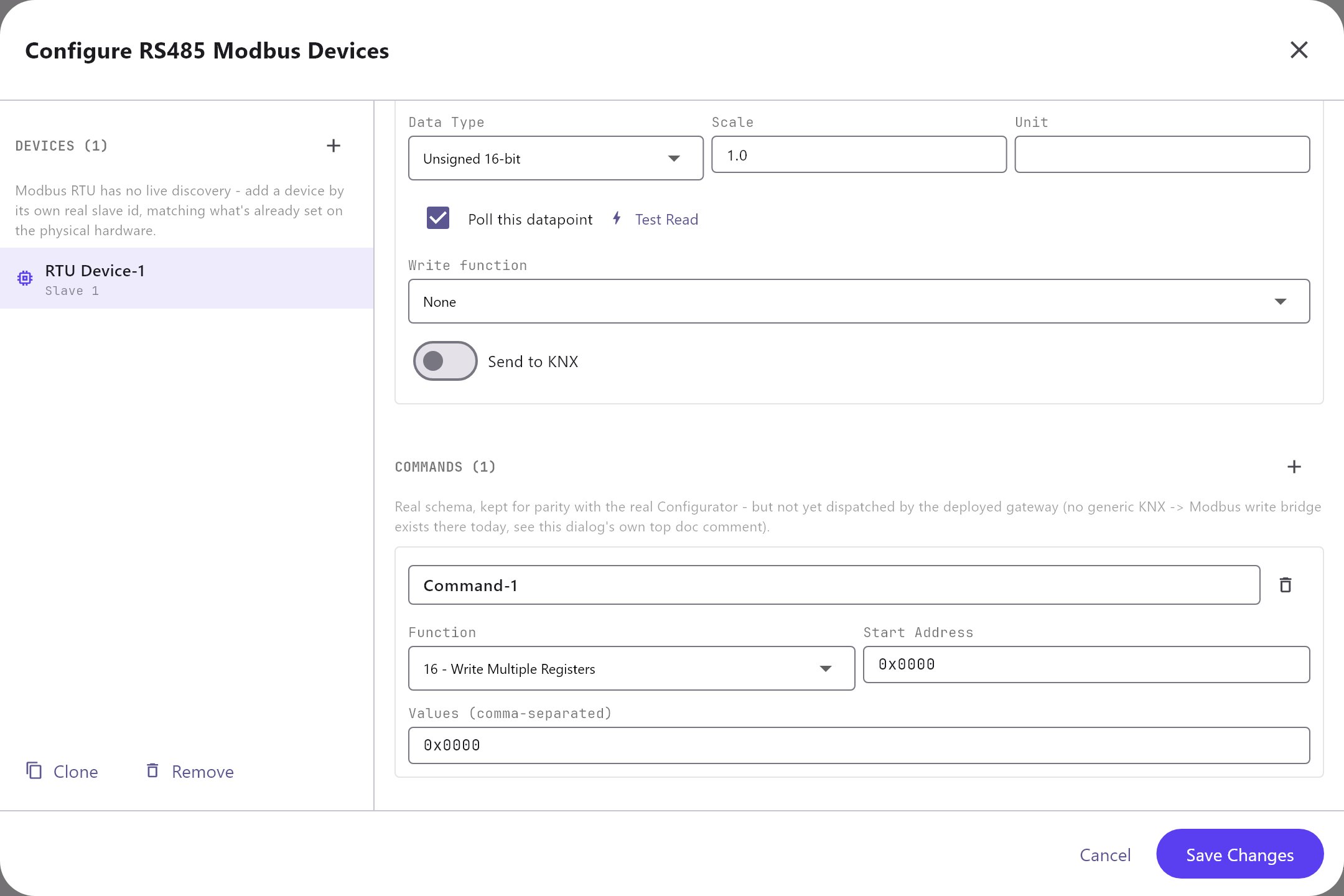
The gateway sends one request per datapoint, so two datapoints on the same register (two bits of one status word) cause two requests.
#Identity
| Field | Meaning |
|---|---|
| Name | A readable name, shown in pickers as Device name - Datapoint name. |
| Reusable value ID | The identifier other parts of the project use to pick this value. It is generated as modbus:<device>.<datapoint> in lower case, each run of other characters becoming an underscore, for example modbus:rtu_device_1.datapoint_1. It does not change if you rename the device or datapoint later; edit it by hand if you want that. It must be unique. |
#Addressing and type
| Field | Meaning |
|---|---|
| Data address | The zero-based protocol address, 0x2000 or 8192 (section 1). |
| Read function | 01 Read Coils, 02 Read Discrete Inputs, 03 Read Holding Registers (default), 04 Read Input Registers. |
| Write function | None (default, read only), 05, 06, 0F or 10. A datapoint with a write function can be written by a Write Modbus Value action or from a KNX group address (section 6). |
| Write from KNX group address | Shown when a write function is chosen. Optional. A KNX write to this group address is sent to the register: the value is read with the DPT below, put through the datapoint's scale, offset and data type, and written with the write function. Leave it empty if nothing on the KNX bus should write this register. |
| Data type | How the reply is decoded (table below). |
| Register count | Registers or coils to read, 1 to 64. The minimum is 2 for the 32-bit types and 1 for the rest. |
| Bit number | 0 to 15. For the Bit / coil type on a register read. Leave it empty to get 1 whenever the register is not zero, and always leave it empty for coil and discrete input reads. |
| Word order | ABCD, BADC, CDAB or DCBA. 32-bit integers and floats only. |
| Data type | Result | Registers used |
|---|---|---|
| Bit / coil | A coil or discrete input: 0 or 1. A register: the bit named in Bit number | First |
| Unsigned 16-bit | 0 to 65535 | First |
| Signed 16-bit | -32768 to 32767 | First |
| Unsigned 32-bit | 0 to 4294967295, using the word order | First two |
| Signed 32-bit | The same bytes as a signed number | First two |
| Float 32-bit | IEEE 754 single precision | First two |
| String | ASCII text, two characters per register, trailing zeros and spaces removed | All |
| Raw words | A list of the register values, unscaled | All |
Registers beyond those used are read but ignored, so keep Register count at the minimum for the numeric types.
#Value processing
| Field | Meaning |
|---|---|
| Scale / offset | For numbers, value = raw x scale + offset, rounded to six decimals. The first field is the scale (default 1), the second the offset (default 0). A raw 253 with scale 0.1 gives 25.3. A scale of 0 is stored as 1. Strings and raw words are not scaled. |
| Unit | Text shown with the value, for example degC or kWh. |
#Polling and live value
| Field | Meaning |
|---|---|
| Poll | On by default. When off, the gateway never reads this datapoint, so it never has a value. |
| Latest value | The last reading from the deployed gateway with its unit, or --. Refresh reads again, and the dialog refreshes itself every five seconds. It needs the gateway address in Settings. |
The gateway reads all polled datapoints one after another in device-list order, one request each, and starts the next round two seconds after finishing the previous one. It adds a 50 ms pause when the next datapoint belongs to another slave. There is no per-datapoint or per-device interval. A failed read does not stop the round: the datapoint is flagged stale, keeps its last value, and the gateway moves on.
#Publishing to KNX
| Field | Meaning |
|---|---|
| Send value to KNX | Off by default. Publishes this datapoint to a KNX group address. |
| KNX group address | The three-level address, for example 7/0/1. |
| KNX datatype | DPT 1.001 switch, 5.001 percent, 7.001 unsigned 2 byte, 8.001 signed 2 byte, 9.001 2 byte float (default), 9.020 voltage, 12.001 unsigned 4 byte, 13.001 signed 4 byte or 14.001 4 byte float. It must match the DPT of the group object. |
| Only on change | On by default. When on, an unchanged reading is not sent again. |
| Min change | Default 0. A numeric reading counts as changed when it differs from the last sent value by at least this amount. With 0, any difference counts but an identical reading does not. |
How publishing behaves:
- The first successful reading after the Modbus engine starts is always published, and so is the first reading after a failed one. With Only on change off, every reading is published.
- For numbers the test is "difference at least Min change". With Min change 0 any difference counts, and an identical reading is not sent again. Set a small Min change (0.1 for a temperature, 1 for a 0 or 1 status bit) to also ignore tiny movements.
- The same test decides whether connected apps get a live update. The stored latest value is refreshed on every successful read regardless.
- Each KNX write happens inside the poll round and can take up to 3 seconds when KNX is slow, so many published datapoints lengthen the round.
- DPT 1.001 sends 0 as off and anything else as on. DPT 5.001 expects 0 to 100 percent and is clamped. DPT 7.001 and 8.001 are rounded to whole numbers.
The gateway's KNX engine must be running. See KNX basics for installers.
#6. Commands
A command is a named write that sends one or more values to the device in one frame.
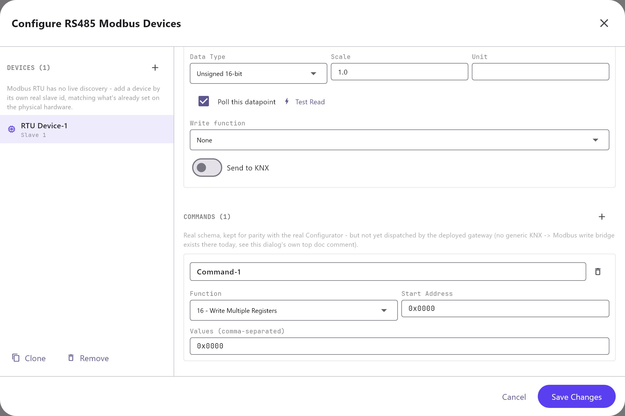
| Field | Meaning |
|---|---|
| Name | A readable name. |
| Reusable command ID | Generated as modbus-command:<device>.<command>, like a value ID. |
| Write function | 05 Write Single Coil, 06 Write Single Register, 0F Write Multiple Coils or 10 Write Multiple Registers. |
| Start address | Protocol address of the first register, in the same notation as Data address. |
| Values | Register values separated by commas, hex with 0x or decimal, for example 0x1DC7, 0x1111. Functions 05 and 06 take one value. |
Use function 10 (16 decimal) with several comma-separated values when a device needs two or more registers written together, for example a key register plus a command register. They travel in one frame, so nothing else on the bus can fall between them. The device answers with a short frame repeating the start address and register count.
#Sending a command or a value
Commands and write functions run when something asks the gateway to:
- Action Button, Run Modbus Command. Choose Run Modbus Command in the button's command list (category Modbus) and pick the command from the list of every command on every Modbus device. Pressing the button sends it.
- Action Button, Write Modbus Value. Choose Write Modbus Value, pick a datapoint that has a Write function, and enter the value. The value is turned back into register data through the datapoint's own scale, offset, data type and word order: with scale 0.1 and a 16-bit datapoint, 21.5 is sent as 215. A 32-bit or float datapoint needs write function 10 (two registers at once). A bit datapoint needs a coil function (05 or 0F), where any value other than 0 means on.
- Sun and prayer events can run the same two commands at a fixed time.
- Logic Studio. The Run Modbus Command block sends a chosen command when its input turns on (pick the command in the block's settings). The Command block can also run Run Modbus Command or Write Modbus Value from its command list; put the id or the value in its parameters.
- A KNX group address. Give a datapoint a Write function and fill in Write from KNX group address: every KNX write to that address is sent to the register. If the same group address also carries the datapoint's status (Send value to KNX), the gateway ignores the echo of its own status telegram, so a value is never written back to the device it came from.
The button's own Require PIN and User access rules apply. A failed write shows the reason on the button's screen (the device refused it, did not answer, or is switched off in the project), after the Retries you set. Commands are sent over the device's own bus: a serial bus that is not polling is opened just for the write.
#7. Built-in device profiles
A profile fills in datapoints and commands for a known device. Check it against your device's manual and firmware; its addresses are sent exactly as stored.
| Profile (as listed) | Datapoints | Commands |
|---|---|---|
| Generic Modbus RTU | One starter: Datapoint-1, 0x0000, function 03, unsigned 16-bit | One starter: Command-1, function 10, 0x0000, value 0x0000 |
| Daikin - Daikin VRV Home Automation I/F (VRV Modbus adapter) | 7 for unit 1-00, function 04: adapter status, on/off bit, fan volume, operation mode, set point and room temperature (signed 16-bit, scale 0.1, degC), malfunction bit | 3 for unit 1-00 (function 10, start 42001, three registers): control block, On, Off |
| Fronius - Tauro ECO Inverter (SunSpec float map) | 48, function 03: AC and DC current, voltage, power, frequency, power factor, session energy and cabinet temperature as 32-bit floats; identity strings (polling off); operating state, event bitmasks, nameplate ratings, PV and grid bits, lifetime energy and the MPPT block with scale factors | 11 (function 06): connect and disconnect, power limit and its enable and disable, power factor and its enable and disable, reactive power and its enable and disable |
| MEBAY - MEBAY DC6xD MK2 Generator Controller | None | 1: Keyboard command block, function 10, start 0x2000, values 0x1DC7, 0x1111 |
| Socomec - Socomec UPS JBUS/MODBUS (Netys, Itys, Masterys) | 21, function 03: status bits at 0x0020 and 0x0021 (mains present, inverter on, load on inverter, load on battery, battery low, battery OK), alarm bits at 0x0040, load, battery capacity, voltages, current, frequencies, battery voltage, temperature, remaining backup time, output power | 5 (function 06 at 0x05B0): alarm reset, UPS off, buzzer enable, buzzer off, immediate battery test |
| Comwintop - CWT-WLS Water Level Sensor | 1: Water Level, 0x0016, function 03, float 32-bit, two registers, unit m | None |
| Temp/Humidity/Dew Point Transmitter (2-Relay) (generic RS485) | 13: temperature, humidity and dew point (0x0000 to 0x0002, signed 16-bit, scale 0.1), plus 10 configuration registers (device address, baud rate, parity, auto-report interval, and source, pull-in and release of each relay) with Write function 06 and Poll off | None |
- Daikin. The datapoints carry the numbers printed in the adapter documentation (30001, 32001 and so on) literally. Check each one with the Modbus Register Test before relying on it. For air conditioning use the AC Manager, which has its own register handling for the adapter.
- Fronius. Pair it with the Solar Manager. The addresses are hex, already converted from the 1-based document numbers.
- MEBAY. The Genset Manager supplies the status and sends the start and stop block itself.
- Socomec. Select the device in the UPS Manager.
- Comwintop. Set the sensor's own unit register to metres of water once, with the vendor's tool, so the value reads directly as height in metres. Water Tank Pump Control can use this datapoint as its level source.
- Transmitter. The two relays switch on the device itself, from thresholds stored in the device.
#8. Using the values
Every polled datapoint becomes a reusable value that other parts of the project can pick.
- Analog Value: set Protocol to System Object, then pick the datapoint under System Value > Modbus RTU. The value is already scaled by the datapoint, so do not scale it again with the object's Factor. See Analog Value. The same picker exists on State Action, Generator Panel, UPS Panel (generic) and Solar Panel (generic).
- KNX: turn on Send value to KNX (section 5).
- Managers: the AC Manager, Genset Manager, UPS Manager and Solar Manager each have a Modbus RTU Device dropdown listing the devices you set up here. The AC and Genset managers list RS485 devices; the UPS and Solar managers list RS485 and RS232 devices. Configure the device first, then pick it. The manager reads and controls it with its own register map, in addition to your datapoints.
- History and graphs: the History Recorder can record a datapoint (source Modbus), and a Graph plots the history.
- Logic: Logic Studio has a System Value input and a System Value Changed trigger. The MQTT Client can publish system values.
A value that has not been read successfully for 15 seconds is flagged stale.
#9. Worked examples
These use generic devices on an RS485 bus, each at Slave ID 1. Use the addresses from your own manual.
#a) A temperature in a holding register, scale 0.1
A room sensor documents its temperature as holding register 40001, signed, in tenths of a degree.
| Field | Value |
|---|---|
| Name | Room temperature |
| Data address | 0x0000 (40001 minus 40001) |
| Read function | 03 - Read Holding Registers |
| Data type | Signed 16-bit |
| Register count | 1 |
| Scale / offset | 0.1 / 0 |
| Unit | degC |
First test it with the Modbus Register Test (RS485, Slave ID 1, FC3, Address 0, Count 1). At 25.3 degrees it returns Registers: 253 and the raw frame 01030200fd79c5, and the gateway shows 253 x 0.1 = 25.3. A raw 65526 is negative in two's complement: as signed it is -10, shown as -1.0, but as unsigned it would wrongly show 6552.6. On an Analog Value use Decimal Digits 1 and turn Sign on so a negative temperature keeps its minus.
#b) A 32-bit energy counter and its word order
An energy meter documents total energy as two holding registers from 40257, unsigned 32-bit, in units of 0.01 kWh.
| Field | Value |
|---|---|
| Name | Total energy |
| Data address | 0x0100 (40257 minus 40001 is 256) |
| Read function | 03 |
| Data type | Unsigned 32-bit |
| Register count | 2 |
| Word order | CDAB |
| Scale / offset | 0.01 / 0 |
| Unit | kWh |
The Register Test (Address 256, Count 2) returns Registers: 34464, 1 with raw frame 01030486a000011299. The first register is 0x86A0 and the second 0x0001. With the default ABCD the gateway joins them as 0x86A00001, which is 2258632705 and clearly wrong. With CDAB (low word first) the number is 0x000186A0 = 100000, and x 0.01 gives 1000 kWh. If the meter display also shows 1000 kWh, CDAB is right. If neither ABCD nor CDAB matches, try BADC and DCBA.
#c) Single bits from a status register
A pump controller documents a status word at holding register 40017: bit 0 Running, bit 1 Fault, bit 3 Remote mode.
Create three datapoints that share Data address 0x0010 (40017 minus 40001 is 16), Read function 03, Data type Bit / coil, Register count 1 and Scale / offset 1 / 0. Only the name and Bit number differ.
| Name | Bit number |
|---|---|
| Pump running | 0 |
| Pump fault | 1 |
| Remote mode | 3 |
If the register reads 9 (binary 1001; the Register Test at address 16 shows Registers: 9, raw frame 01030200097842), the datapoints show Running 1, Fault 0 and Remote mode 1. To send a flag to KNX, turn on Send value to KNX, enter the group address, choose DPT 1.001 and set Min change to 1 so that only a real change between 0 and 1 is sent. If the manual counts bits from 1, or from the most significant end, convert first: this field counts from 0 at the least significant bit.
#d) A setpoint register with function 06, and its status on KNX
A boiler controller documents its temperature setpoint as holding register 40513, signed, in tenths of a degree, writable with function 06.
| Field | Value |
|---|---|
| Name | Boiler setpoint |
| Data address | 0x0200 (40513 minus 40001 is 512) |
| Read function | 03 |
| Write function | 06 - Write Single Register |
| Data type | Signed 16-bit |
| Register count | 1 |
| Scale / offset | 0.1 / 0 |
| Unit | degC |
| Send value to KNX | On |
| KNX group address | 5/1/10 |
| KNX datatype | DPT 9.001 - 2 byte float |
| Only on change | On |
| Min change | 0.1 |
A raw 215 is shown as 21.5 and sent to 5/1/10; thanks to Min change nothing more is sent until the setpoint moves by at least 0.1. The Write function entry records that the register accepts function 06. Writing 21.5 degrees would be the frame 0106020000d7c82c (slave 1, function 06, address 0x0200, value 215). As the warning in section 6 says, the current gateway does not send writes for generic datapoints, so this example reads the setpoint and publishes it; change the setpoint on the controller itself.
#e) A two-register command with function 16
A drive documents a command block at 0x0300: the first register must hold the key 0x00A5 and the second the command, 0x0001 for start. Both must arrive in one frame.
| Field | Value |
|---|---|
| Name | Drive start |
| Write function | 10 - Write Multiple Registers |
| Start address | 0x0300 |
| Values | 0x00A5, 0x0001 |
The request is 0110030000020400a5000136bc (slave 1, function 16, start 0x0300, two registers, four data bytes, CRC) and the device replies 011003000002418c, repeating the start address and register count. The five bytes 0190030c01 would be an exception reply (function 16 plus 0x80, then code 03, illegal data value): the drive rejected the key or the command. The warning in section 6 applies here too: the definition is stored, but the gateway does not send generic commands yet. The Genset Manager sends a block of exactly this shape to a MEBAY controller by itself.
#10. Commissioning and verification
Work in this order: wiring, serial settings, a test read, one datapoint, then the rest.
#Modbus Register Test
Deploy first, with the serial interface enabled and its settings entered. Then click Diagnostics in the toolbar, open the Other Engines tab and use the Modbus Register Test card. The Configurator needs the gateway address in Settings and a paired deploy token (Deploying to a gateway).
| Field | Meaning |
|---|---|
| Bus | RS485 or RS232. |
| Slave ID | 1 to 247. |
| Function | FC3 Holding Registers or FC4 Input Registers. |
| Address | 0 to 65535, a decimal zero-based number. Convert hex addresses first. |
| Count | 1 to 125 registers. |
Click Read. On success the card shows Registers: with the values in decimal, and the Raw frame, the whole reply in hex: slave ID, function, byte count, data and two CRC bytes. On failure it shows Read failed with the reason, such as timeout reading slave 1 function 3 (no reply) or slave 1 returned Modbus exception 2 (the device refused the address). The test waits up to 1.5 seconds. It needs no datapoint and shares the bus with normal polling; with no polled device the gateway opens the port just for the test. Use it first on every new device.
#Bus table
The same tab lists RS485 and RS232:
| Column | Meaning |
|---|---|
| State | READY: the port is open and devices are polled. OFFLINE: configured but the port could not be opened; the last error is shown. PLANNED: not configured, or no enabled device with a polled datapoint. |
| Device Path, Baud | The port and speed in use. |
| Devices | Devices being polled. |
| OK / Errors | Successful and failed requests since the Modbus engine last started. A deploy that changes serial settings, a device, a datapoint or a manager restarts it and resets the counters. |
| Last Poll | When the last round finished. |
On a healthy bus OK grows and Errors stays near zero. Refresh updates the table.
#The gateway console log
Open the gateway console in a browser (see Gateway console and logs), go to the Monitor tab and set Log source to Modbus. Server Logs then shows the latest 80 lines mentioning Modbus. The lines to know:
| Log line | Meaning |
|---|---|
[modbus] polling 12 mapped datapoints on /dev/ttyS0 | The bus started with 12 polled items (datapoints and manager reads). |
[modbus] modbus:boiler.room_temperature = 21.5 | A reading was accepted as changed. An unchanged reading is not logged. |
[modbus] modbus:boiler.room_temperature published -> 5/1/10 = 21.5 | The value was written to KNX; failed: ... follows if the write failed. |
[modbus] timeout reading slave 3 function 4 | No valid reply from slave 3 within the timeout. |
[modbus] slave 3 returned Modbus exception 2 | The device answered and refused. The code is in decimal. |
[modbus] read error: ... or write error: ... | The serial port failed. The gateway then logs reopening /dev/ttyS0 after ... and reopened /dev/ttyS0 or reopen failed: .... |
[modbus] rs485 startup failed: Could not configure /dev/ttyS0: ... | The port could not be set up. Check Linux device. |
A reply with a bad CRC is ignored and so appears as a timeout. The built-in managers log under their own tags, for example [genset] or [ac].
#11. Troubleshooting
#Device does not respond
| Symptom | Likely cause | Fix |
|---|---|---|
timeout reading slave N on every request, Register Test fails | A and B swapped, or wrong bus | Swap A and B at the device. Check Bus in the test. |
| Same, wiring checked | Baud, parity, data or stop bits differ from the device | Compare the interface page with the device, then deploy again. |
| Same | Wrong Slave ID | Read it from the device display or manual and test other IDs. |
| One device answers, another never does | Duplicate Slave IDs, or other serial settings on one device | Unique IDs, identical serial settings. |
| Timeouts come and go | Missing termination, long unscreened cable, a second master | Terminate both ends, use twisted pair, keep one master. |
Bus OFFLINE, or the deploy reports RS485 enabled but not connected (check device path/wiring) | The port could not be opened | Check Linux device, and that the interface is enabled and deployed. |
| Bus PLANNED | No enabled device with a polled datapoint, or interface disabled | Enable the interface, the device, and Poll on one datapoint. |
#Wrong register or wrong value
| Symptom | Likely cause | Fix |
|---|---|---|
Modbus exception 2 | Address not in that area | Check the Read function and the conversion in section 1. Typing Modicon 40001 as the address is a common mistake. |
| Plausible but wrong number | Off by one, the manual is 1-based | Subtract 1 and test the neighbours. |
| Address behaves as 0 | Hex typed without 0x, or with h | Type 0x0100 or the decimal number. |
| 10 or 100 times too large | No scale | Scale 0.1 or 0.01. |
| Negative value shows as 65xxx | Unsigned type | Signed 16-bit or Signed 32-bit. |
| 32-bit number or float is nonsense | Wrong word order | Try CDAB, then BADC and DCBA. |
| Off by a fixed amount | Offset missing | Set the offset (second Scale / offset field). |
| Wrong bit | Bit counted differently | Bit number counts from 0 at the least significant bit. |
| Right in the datapoint, wrong on the dashboard | Scaled twice | Keep the object's Factor at 1. |
-- | Poll off, device disabled, or reads failing | Check the toggles and the log. |
#Writes are ignored
| Symptom | Likely cause | Fix |
|---|---|---|
| A button that runs a command or writes a value shows an error | The device refused the write (exception code), did not answer, or is disabled | Read the message. Check the device is enabled, the address and function in its manual, and that a datapoint has a Write function. |
| A manager write fails with an exception | The device rejects the value or is write-protected | Read the code in the table below. |
#Unstable or slow readings
| Symptom | Likely cause | Fix |
|---|---|---|
| Slow updates | A long round: many datapoints, one request each | Remove unneeded datapoints, set Poll off, disable unused devices. Each unreachable datapoint costs a full timeout every round. |
| Occasional timeouts on a slow device | Timeout too short | Raise Timeout (ms), for example to 2000. |
| Values flagged stale | No successful read in 15 seconds | Fix the timeouts above. |
| Random errors | Cable, grounding, termination | Screened twisted pair, correct termination, common ground where required. |
#Value not on KNX
| Symptom | Likely cause | Fix |
|---|---|---|
| Nothing is sent | Send value to KNX off, or no group address | Turn it on and enter the three-level address. |
| Sent once, then nothing | Only on change and the reading is steady | Expected. It is sent again when the Modbus engine restarts. |
| A telegram on every poll | Only on change is off, or the reading really changes every time (a noisy sensor) | Turn Only on change on and set a small Min change. |
| Wrong number on the group address | DPT does not match | Use the DPT of the group object in ETS. |
Log shows published ... failed: | KNX write failed or timed out | Check the KNX engine (KNX basics for installers). |
#Modbus exception codes
The log prints the code in decimal.
| Code | Name | Typical meaning on site |
|---|---|---|
| 01 | Illegal Function | The device does not support this function. Try 03 instead of 04, or the reverse. |
| 02 | Illegal Data Address | The address, or the address plus count, is outside the map. Check the area and conversion, and reduce Register count. |
| 03 | Illegal Data Value | The count or value is not accepted, for example reading half of a 32-bit pair, or a value out of range. |
| 04 | Server Device Failure | The device failed while handling a valid request. Retry and check the device. |
| 05 | Acknowledge | The device accepted a long operation. Rare. |
| 06 | Server Device Busy | The device is busy. Retry later or reduce the polling load. |
| 10 | Gateway Path Unavailable | Behind a Modbus gateway or converter (hex 0A). |
| 11 | Gateway Target Device Failed to Respond | The converter cannot reach the end device (hex 0B). |
#Quick diagnostic procedure
- Check power, then wiring: A to A, B to B, ground reference, termination at both ends.
- Compare the device's baud rate, data bits, parity, stop bits and Slave ID with the interface page. Deploy.
- In Diagnostics > Other Engines, check the bus is READY and shows the right device path.
- Run the Modbus Register Test on a register the manual documents: the right bus, Slave ID, FC3, address 0, count 1.
- On a timeout, repeat steps 1 and 2, then try FC4 and another Slave ID. On an exception, fix the address or function using the table above.
- Once a register reads, compare it with the device display and adjust type, scale and word order until they agree.
- Create the datapoint and compare Latest value with the device.
- Open the gateway console, Monitor, Log source Modbus, and watch for
timeoutorexceptionlines while it polls. - Add KNX publishing and test the group address with the console's Send Telegram form or the Bus Messages list of the console's Monitor tab.
- Add the remaining datapoints and watch OK / Errors for a few minutes.
#12. Limits and what is not supported
- Master only. The gateway reads serial devices (RTU) and network devices (Modbus TCP). There is no Modbus slave (server) mode: it cannot act as a Modbus device for another system. Modbus ASCII and Modbus RTU over TCP are not supported.
- Two buses, RS485 and RS232, each an independent master.
- Slave IDs 1 to 247 on a serial bus (broadcast, ID 0, is not available). A Modbus TCP device uses a Unit ID from 0 to 255.
- Reads use functions 01 to 04, one request per datapoint of up to 64 registers. Neighbouring datapoints are not merged into one request.
- Writes use functions 05, 06, 0F and 10, started by an Action Button, a sun/prayer event, a Logic Studio block, a KNX group address (datapoint setting Write from KNX group address) or one of the built-in managers (section 6).
- Polling is one sequential round over all datapoints with a two-second pause between rounds. There is no per-datapoint interval. A serial device that times out is tried again up to Retries times in the same round.
- Register Test reads function 3 or 4 only and takes a decimal address.
- Decoding: 16-bit types use the first register only, 32-bit types the first two.