
4.22Logic Studio
Reference for the Logic Studio visual logic builder: functions, the scheme editor, every block type and how the gateway evaluates them.
Logic Studio is the visual logic builder of the gateway. You draw a scheme of blocks, connect them with links, and the gateway keeps evaluating it, reading KNX values and writing KNX results. This page lists the dialogs, every block type and how the gateway runs a scheme.
#What it does
A logic function is one scheme. A scheme has input blocks that bring in values (a KNX group address, a constant), processing blocks (logic gates, maths, timers, counters, analog filters, a script) and output blocks that write the result to a KNX group address. Typical uses are a light that follows a motion sensor with a timer, a fan that follows two conditions, or a counter of how long a pump has run.
Logic Studio publishes no System Objects. Its results leave as KNX telegrams, so a page object shows a result by being bound to the output's group address.
#Before you enable it
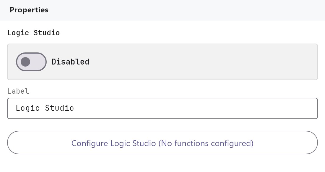
- The service is Disabled by default. Turn Enabled on and deploy the project (see Deploying to a gateway). Each function also has its own Enabled switch.
- Logic Studio reads and writes the KNX bus through the gateway's KNX connection, so the KNX engine must be working.
- Save in the dialog (Save Changes) and deploy again after every change.
#Settings
| Setting | What it does |
|---|---|
| Enabled | Turns Logic Studio on or off. Off by default. |
| Label | The name in the Server tree. Default Logic Studio. |
| Logic Functions | The button Configure Logic Studio opens the dialog. The text in brackets shows how many functions are enabled, for example 1/2 enabled, or No functions configured. |
#The Logic Studio dialog
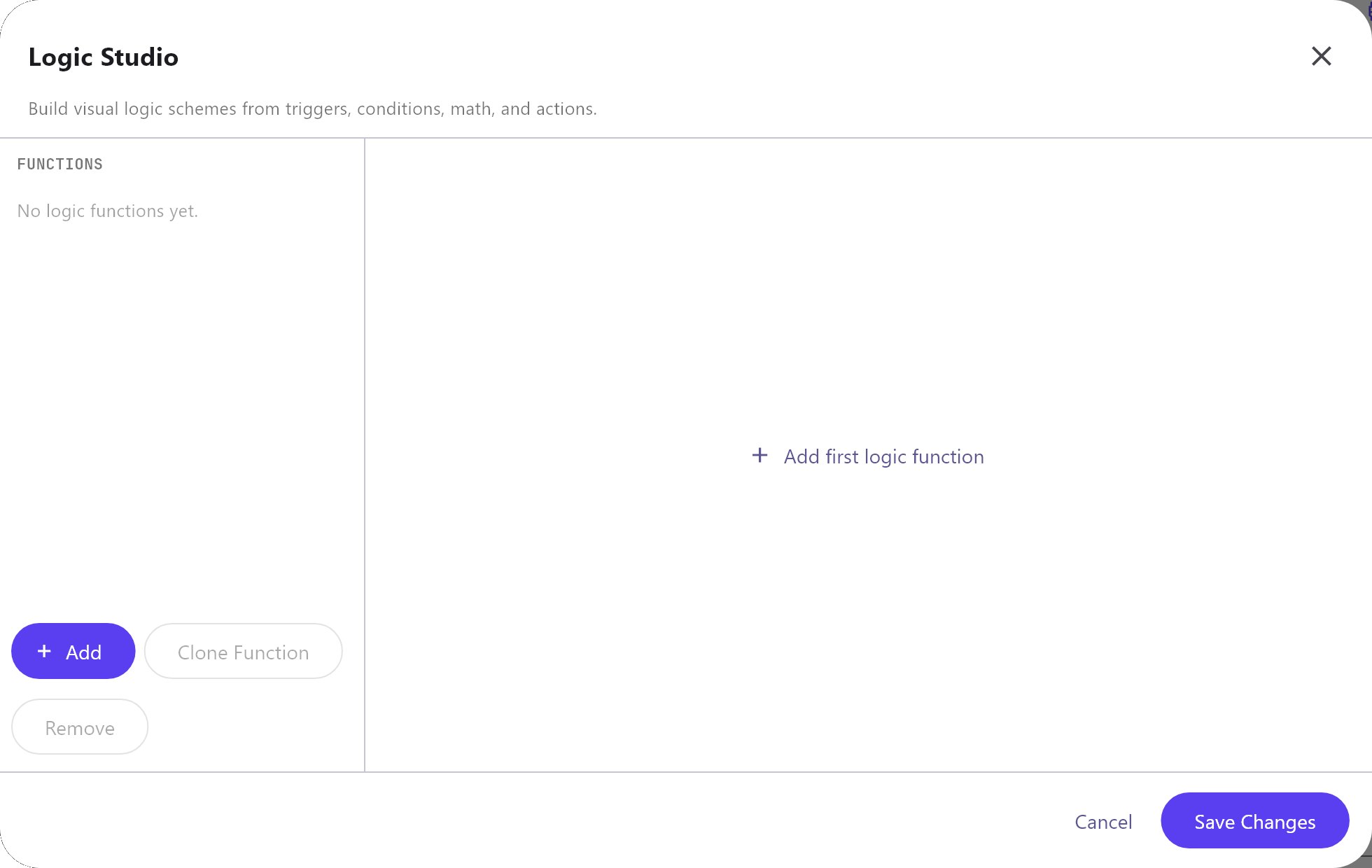
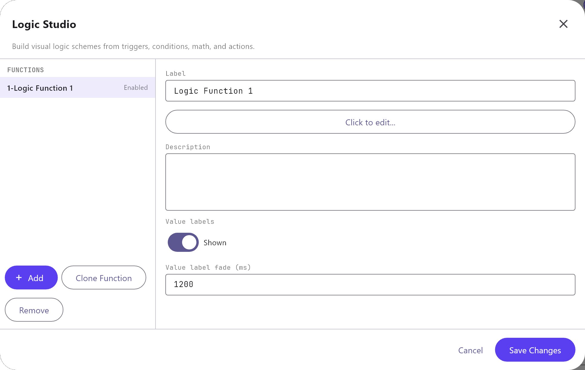
The left column lists the functions as 1-Logic Function 1 with an Enabled or Disabled tag. Add creates a function, Clone Function copies the selected one (with Copy added to its name) and Remove deletes it. Selecting a function shows its properties:
| Field | What it does |
|---|---|
| Label | The function's name. Default Logic Function N. |
| Scheme | Click to edit... opens the scheme editor. |
| Description | Free text for your own notes. |
| Value labels | Shown (default) or Hidden. Shows the live value of each block while you test. |
| Value label fade (ms) | 100 to 30000, default 1200. How long a changed value stays highlighted. |
Import and Export in the header save and load all functions as logic-studio-functions.json. Importing replaces every function. A file that is not a Logic Studio file shows "Invalid Logic Studio file." Unlike the other dialogs, Save Changes here saves the session ("Logic Studio saved."), and Cancel or the close button asks you to confirm before it discards unsaved changes.
#The scheme editor
Select a function and press Click to edit... to open the editor. It has three parts: the function list and Block Palette on the left, the canvas in the middle and the Properties inspector on the right. Back to collection returns to the function list.
- Add a block: drag an entry from the palette onto the canvas, double-click it, or select it and press Add Block. Search blocks... filters the palette by name. The palette groups are Inputs, Outputs, Analog, Counters, Logic, Math, Timers, Scripting, Logic Module Sheet, Conditions and Comment.
- Connect blocks: drag from the out point of a block to one of the input points of another. A block shows one input point per input (set by Inputs, 1 to 64), from top to bottom, and the block grows taller to hold them. Where the order of the inputs is fixed, the points are named (On/Off Delay:
InputandReset; Comparator:Input 1andInput 2), otherwise they are numbered. Dropping a link on a point that already has one replaces it. A block with a gate also has a gate point. Click a link to select it, and use its x button to remove it. The inspector's Connect to list does the same without dragging, and a selected link has an Input port list to move it to another point. - Toolbar: the function name, the function's Enabled switch, Live gateway test, the Grid switch and grid size (5 to 100, default 20), zoom out and in (10 to 200 percent), 100% and Fit. Ctrl and the mouse wheel also zoom. The canvas starts at 1040 by 560 units and grows as you place blocks further right or down, so a scheme with many blocks (for example 15 inputs feeding one Or) always has room.
- Live gateway test: with Value labels shown, each block displays its current value. The editor reads it every second from the gateway, so the project must be deployed and the gateway reachable from the Configurator.
#Block properties
Select a block to see its inspector. These fields exist for every block type.
| Field | What it does |
|---|---|
| Label | The name on the block. |
| Category, Type | Changing either resets the block's parameters to that type's defaults. |
| X, Y | The block's position. |
| Type-specific fields | Described in the block tables. |
| Inputs | 1 to 64. The number of input points the block shows. It is also the number of inputs Await all inputs waits for. A point that has a link is never hidden, even if you lower this number. |
| Output | On change, Every update, Interval, Threshold or Threshold/interval. Only the counter blocks use it. All other blocks ignore it. |
| Gate | For every block except inputs and outputs. When on, the block works only while a link to its gate point carries 1. A gate-enabled block with no gate link never runs. |
| Await all inputs | The block waits until every one of its linked inputs, up to the Inputs number, has a value. |
| Inverted gate | The gate is open while its value is 0. |
| Force output sending | When the gate opens, a connected KNX output writes its value even if it did not change. |
| Input links, Output links | The links of this block. Click one to select it. |
| Clone block, Remove block | Copy or delete the block. |
A link has a name, a source and target block, and an Enabled switch. A disabled link is ignored.
#Block reference
A value counts as true when it is 1, true, on, yes or any number other than 0. A logic result is written as 1 or 0.
#Inputs
| Block | Inputs | Output and parameters | Run? |
|---|---|---|---|
| KNX Input | none | The latest value on a KNX group address. KNX Group, Input type (a data type from DPT 1.001 to 232.600, default 1.001) and Value at startup: Read current value (default, reads the bus once at start), Wait for a new telegram, 0 until first telegram or 1 until first telegram. It updates when a write or response telegram arrives. | Yes |
| Constant Value | none | A fixed value. Value type Bit (default, becomes 1 or 0), Number or String, and Value. | Yes |
| System Value, System Status, Value Store | none | Three names for one block. System status picks a reusable value and the block outputs its latest value: a Network I/O virtual input, a Rule gateway value, a value of the Value Store (listed as Value Store - name) or any other value the gateway publishes, such as a Modbus datapoint, a Zigbee value, the weather or solar values. The block has no output until the gateway has a value. | Yes |
| Sheet Input | none | Appears in the palette. | No |
#Outputs
| Block | Inputs | Output and parameters | Run? |
|---|---|---|---|
| KNX Output, KNX Write | 1 | Writes the linked value to a KNX group address. Group address and Output type (data type). The Value field is not used: the value always comes from the linked block. For DPT 1 and 2 the value is written as 1 or 0. It writes only when the value changes, or when forced by the gate. | Yes |
| Command | 1 | Runs a system command when its input is true. Trigger: On trigger (default) or On parameter value change. Command: choose from the command library. Command parameters: a JSON text such as {"groupAddress": "1/1/5", "value": "1"}. The KNX write commands, the Modbus commands and the Network I/O commands do anything. A KNX write needs a groupAddress parameter. If the parameters hold a non-empty value, it is written, otherwise the input value. With On trigger the command runs each time the input turns from 0 to 1, and not again while the input stays 1. For repeated actions use KNX Output. | Partly |
| Run Modbus Command | Trigger, Modbus command | Sends the chosen command from a Modbus device's Commands tab when its input turns on. | Yes |
| Network Output | Trigger | Runs the network output you choose (Network output, from the Network I/O gateway) when its input turns on. The value of the input fills {value} in the output's payload. | Yes |
| Set Value Store | Trigger | Stores a value in the Value Store and publishes it to the bus. Trigger (default On parameter value change, which stores every new value of the input, also 0). Stored value: the value to set. Value: leave empty to store the value of the input, or type the fixed value to store. | Yes |
| Sheet Output, Notification | - | Appear in the palette. | No |
#Logic
| Block | Inputs | Output and parameters | Run? |
|---|---|---|---|
| And, Nand | 2 or more | 1 if all inputs are true (Nand: not all). | Yes |
| Or, Nor | 2 or more | 1 if any input is true (Nor: none). | Yes |
| Not | 1 | The opposite of the input. | Yes |
| Xor | 2 or more | 1 if an odd number of inputs are true. | Yes |
| XNOR | 2 or more | 1 if an even number of inputs are true. | Yes |
| Xand | 2 or more | 1 if all inputs have the same value (all true or all false). | Yes |
| Filter | 1 | Turns input 1 or 0 into an output. Filter type (default 1 -> 1 / 0 -> 0): 1 -> - / 0 -> -, 1 -> - / 0 -> 0, 1 -> - / 0 -> 1, 1 -> - / 0 -> Toggle, 1 -> 0 / 0 -> -, 1 -> 0 / 0 -> 1, 1 -> 1 / 0 -> -, 1 -> 1 / 0 -> 0, 1 -> Toggle / 0 -> -, 1 -> Toggle / 0 -> Toggle (a dash means no output). Delay: Do not use, Use if input is 1, Use if input is 0 or Use always, with Delay base time (Milliseconds, Seconds, Minutes, Hours) and Delay factor. A new input replaces a delayed one that has not fired. | Yes |
| If | 3 | Input 1 is the condition, input 2 the value when true, input 3 the value when false. | Yes |
| Latching Relay | 2 | Input 1 sets the output to 1, input 2 resets it to 0, otherwise it holds. Behaviour: Set input dominant or Reset input dominant (default) decides a tie. The state is lost when the gateway restarts. | Yes |
| Pulse Relay | 3 | Input 1 toggles the output on each rising edge (0 to 1), input 2 sets, input 3 resets. Behaviour as for the latching relay. | Yes |
| Logic Matrix | 3 or more | Input 1 is a 0-based selector, the other inputs are choices. The output is the choice the selector points to. Data type, Default input (0 to 255, used when the selector has no value) and Update every control value (saved, not used). | Yes |
#Math
Math blocks use only the numeric inputs and produce a number. A block with no numeric input gives no output.
| Block | Inputs | Output and parameters |
|---|---|---|
| Abs | 1 | The absolute value of input 1. |
| Add | 2 or more | The sum. |
| Average | 2 or more | The mean. |
| Division | 2 | Input 1 divided by input 2. No output if input 2 is 0. |
| Linear Combination | 2 or more | The sum of each input times its load. Loads: comma-separated numbers, default 1,1. An input without a load uses 1. |
| Logarithm | 2 | The logarithm of input 2 to the base of input 1. No output if the base is 1 or less, or input 2 is 0 or less. |
| Math Expression | 3 | Evaluates an expression. Variables: comma-separated names, default a,b,c, matched to the input points in order. Expression: digits, + - * / %, brackets, commas, variable names and the functions abs, acos, asin, atan, atan2, ceil, cos, exp, floor, log, max, min, pow, round, sin, sqrt, tan. Default a + b. A result that is not a finite number gives no output. |
| Max, Min | 2 or more | The largest or smallest input. |
| Multiplication | 2 or more | The product. |
| Pow | 2 | Input 1 to the power of input 2. |
| Remainder | 2 | The remainder of input 1 divided by input 2. No output if input 2 is 0. |
| Round | 1 | Rounds input 1. Decimals 0 to 10, default 0. |
| Subtract | 2 or more | Input 1 minus the others. With one input, the negative of it. |
All math blocks are run.
#Timers
Times use Milliseconds, Seconds, Minutes or Hours (default Seconds). Timer state is kept in memory and is lost on a restart. The gateway checks timers once a second, so times are accurate to about a second.
| Block | Inputs | Output and parameters | Run? |
|---|---|---|---|
| Continuous Pulse Generator | none (gate) | Alternates 1 and 0, starting with 1. Factor for ON, Time base for ON, Factor for OFF, Time base for OFF (default 1 second each). The gate is on by default, so it runs only while its gate link carries 1. | Yes |
| Pulse Train Generator | 2 | Input 1 rising edge starts a train of Pulse number pulses (default 2), input 2 stops it. Factor and time base for ON and OFF. | Yes |
| Random Generator | none (gate) | Alternates 1 and 0 with random times. Minimum and Maximum factor for ON and for OFF, with a time base each (defaults 1 and 5 seconds). The gate is on by default. | Yes |
| Scheduled Pulse | none (gate) | Outputs 1 for a set time once a day. Scheduled Time (default 08:00) and Factor for pulse duration with a time base. The gate is on by default. If the gateway starts after the scheduled time, the pulse starts at once. | Yes |
| Stairwell Lighting Switch | 1 | A rising edge on the input turns the output on for Time for ON (default 60 seconds). Warning before OFF (default 10 seconds) sets the warning window. Retriggerable (default on) restarts the time on each new edge. Manual OFF (default off) switches off when the input falls to 0. Output connector: Output (default), Warning or Remaining time (seconds). | Yes |
| Stopwatch | 2 | Input 1 runs the watch, input 2 resets it. Trigger policy: Switch (runs while the input is 1) or Toggle (a rising edge starts, the next one reports). Time UoM and Output connector Partial time or Total time (default). | Yes |
| On/Off Delay | 2 | Delays a signal. Input 1 is the signal, input 2 resets the output to 0. When the signal goes to 1 the output follows after the ON delay (Factor and time base for ON delay), and when it falls to 0 the output follows after the OFF delay (default 1 second each). The output is sent only when it changes. | Yes |
#Analog
| Block | Inputs | Output and parameters | Run? |
|---|---|---|---|
| Comparator | 2 | 1 when the difference between the two inputs is above Threshold for ON (default 1), 0 when it is below Threshold for OFF (default 0.5), otherwise it holds (hysteresis). The difference is always positive, so it does not matter which input is larger: the block cannot tell "too low" from "too high". To test a value against a limit, link a Constant Value to the second input. | Yes |
| Comparator / 2 Points Regulator | 2 | The same function as Comparator, under its longer name. Same fields, shown in the inspector as Threshold for ON and Threshold for OFF. | Yes |
| Multi Threshold Filter | 1 | The zone number the input falls in. Zone thresholds: ascending, comma-separated, default 10,20,30. Below the first is 0. | Yes |
| PID Controller | 2 | Input 1 is the measured value, input 2 the setpoint. Sampling time (s) (default 10), Deadband threshold (default 1), Kp, Ki, Kd (default 1 each), Output Min. (0) and Output Max. (100). The output is recomputed once per sampling time and held inside the deadband. | Yes |
| Pulse Width Modulator | 1 | A 1/0 output that is on for a share of each Period (ms) (default 60000, minimum 100). The share follows the input between Input Min. (0) and Input Max. (100). | Yes |
| Ramp | 1 | Moves the output toward the input by Step size (default 1) every Time step (ms) (default 1000, minimum 100). | Yes |
| Range Verifier | 1 | 1 when Threshold Min. (0) <= input <= Threshold Max. (100), else 0. | Yes |
| Threshold Filter, Threshold | 1 | Limits the input. Filter type: Minimum and maximum thresholds (default), Minimum threshold only or Maximum threshold only, with Threshold Min. and Threshold Max.. | Yes |
| Time-based Filter | 1 | Average, minimum or maximum of recent inputs. Computation Average (default), Minimum or Maximum. Window: Last N samples (Sample count 2 to 100, default 30) or Sliding time window (Window duration and Unit). | Yes |
| Thermostat 4 pipes, Thermostat setpoint, Thermostat setpoint reverse | - | Appear in the palette. | No |
#Counters
Counters keep their totals in gateway storage when Reboot survive is on (the default), so they survive a restart. They use the block's Output setting. Besides the choices in the table, Interval and Threshold show Store time interval (ms) (default 60000) and Change percentage (default 5).
| Block | Inputs | Output and parameters | Run? |
|---|---|---|---|
| Maintenance Counter | 2 | Adds up the time input 1 is 1; input 2 resets it. Time UoM (default Hours) and Reboot survive. The result is sent when the input falls to 0. | Yes |
| Statistic Meter | 3 | Input 1 is a growing reading such as an energy meter, input 2 resets, input 3 requests the value (rising edge). It adds each increase to day, week, month and year totals. Statistic output: Current day total (default), Current week total, Current month total, Current year total, the four Previous totals, or Start date. Reboot survive. | Yes |
| Up/Down Counter | 3 | A rising edge on input 1 adds 1, a rising edge on input 2 subtracts 1, and input 3 set to 1 resets the count to 0. The output is the current count. Reboot survive keeps the count across a gateway restart. | Yes |
#Scripting and comments
| Block | Inputs | Output and parameters | Run? |
|---|---|---|---|
| Scripting | 2 | Runs a small script. Parameters: names for the inputs, default parameter1,parameter2. Script: the body of a function that ends with return, for example return Number(parameter1) + Number(parameter2);. Output property: if the script returns an object, the property to use (default output). Timeout (ms): 50 to 10000, default 1000. The script can use Math, Number, String, Boolean, Date, parseFloat, parseInt, isFinite, isNaN and an inputs list. An error or timeout is logged and gives no output. | Yes |
| Comment | - | A note on the canvas. | Not applicable |
#Logic Module Sheet and Conditions
The Logic Module Sheet blocks start something, and the Conditions blocks test a value. Blocks that report an event answer with a pulse: 1 in the evaluation in which the event happened, 0 in the next. Link a pulse to a Command, Network Output or Set Value Store block (set to On trigger) to run it once per event.
| Block | Inputs | Output and parameters | Run? |
|---|---|---|---|
| Time Schedule | none | 1 during the minute Time (HH:MM, project time zone) on the Days listed (mon,tue,wed,thu,fri,sat,sun; empty means every day), otherwise 0. | Yes |
| System Value Changed | none | A pulse when the value with the Reusable value ID changes. Edge: Any change, Rising edge (becomes true) or Falling edge (becomes false). The value found when the gateway starts is not a change. | Yes |
| KNX Telegram | none | A pulse when a telegram arrives on Group address. Event: Write or response, Write only or Response only. Edge: any (default) pulses for every telegram, rising only when the value is true and was not before, falling only when it is false and was not before. | Yes |
| Manual Run, Sheet Input | none | Appear in the palette. Nothing can start them. | No |
| Compare | 1 or 2 | 1 when input 1 passes the test Operator against the second input, or against the Compare value field when no second input is linked, otherwise 0. | Yes |
| Range Check | 1 or 2 | The same test, meant for Between: write the Compare value as min,max (both included). | Yes |
| Threshold Filter (Conditions) | 1 or 2 | Passes input 1 on while the test is true. When it is false the block gives no new output and its last value stays. | Yes |
| Changed | 1 | A pulse when input 1 differs from its previous value. The first value is not a change. | Yes |
| Rising Edge, Falling Edge | 1 | A pulse when input 1 goes from false to true (rising) or from true to false (falling). | Yes |
Operator for Compare, Range Check and Threshold Filter: Equals, Not equals, Greater than, Less than, Between (the compare value is min,max; 10..20 and 10;20 also work) and Contains (the text of input 1 contains the compare value). Numbers are compared as numbers and anything else as text. Changed, Rising Edge and Falling Edge ignore the operator.
#How it works on the gateway
- The gateway evaluates every enabled function once a second. It also evaluates the function at once when a KNX write or response telegram arrives for a group address used by one of its KNX Input blocks.
- Each evaluation runs every block repeatedly, so the order of the blocks on the canvas does not matter.
- A KNX output writes only when its value changed since its last write, with one exception: the first evaluation after the gateway starts writes the output's current value. A scheme that ends in a timer therefore writes
0at start. - Inputs that have no value yet make dependent blocks wait. An And with one input that has no value gives 0.
- The gateway sees its own writes as incoming telegrams. Do not feed a block from the same group address it writes to.
- Counter totals with Reboot survive are saved in gateway storage. Everything else, including latches and timers, starts empty after a restart.
#Example 1: motion sensor to light with a timer
The light follows a motion sensor and stays on for 5 minutes after the last movement.
- Add a function named
Corridor lightand open the scheme. - Add a KNX Input: KNX Group
1/2/10, Input typeDPT 1.001, Value at startup0 until first telegram. - Add a Stairwell Lighting Switch: Time for ON
300with Time base for ONSeconds, Warning before OFF10seconds, Retriggerable on, Manual OFF off, Output connectorOutput. - Add a KNX Output: Group address
1/1/21, Output typeDPT 1.001. - Link KNX Input to the Stairwell block, and the Stairwell block to the KNX Output.
- Save and deploy. A movement telegram (1) on
1/2/10writes1to1/1/21. Each new movement restarts the 5 minutes. When the time ends the gateway writes0.
#Example 2: only when it is dark
Add the lux sensor so the light only comes on at night:
- Add a KNX Input
1/2/11, Input typeDPT 9.004, Value at startupWait for a new telegram, and a Range Verifier with Threshold Min.0and Threshold Max.50. Link the input to the Range Verifier. - Add an And. Link the motion KNX Input and the Range Verifier to it.
- Link the And to the Stairwell block instead of the motion input.
Now motion only starts the timer while the lux value is between 0 and 50. In daylight the And gives 0.
#Example 3: mains failure that survives one phase still being on
In many places a power cut drops one or two phases while the third stays on, sometimes at only about 100 V. A check "all three phases are zero" then never fires. Use the lowest phase instead.
- Add three KNX Input blocks, one for each phase voltage of the meter, Input type the data type your meter uses for voltage.
- Add a Min block with Inputs
3. Link the phases to its input points 1, 2 and 3. - Add a Constant Value, Value type
Number, Value240(the normal voltage). - Add a Comparator / 2 Points Regulator. Link the Min to its point
Input 1and the constant toInput 2. Set Threshold for ON70and Threshold for OFF40. - Add a KNX Output for the "mains failed" flag and link the Comparator to it.
The Comparator turns on when the lowest phase is more than 70 V away from 240 V (below about 170 V), and turns off again when it is less than 40 V away (above about 200 V). Between the two it holds, so a voltage that wobbles around the limit does not switch the flag back and forth. A normal supply at 245 V is only 5 V from 240 V and stays off.
#Example 4: a battery percentage flag
Send a flag to the bus when a UPS battery falls below 90 percent:
- Add a KNX Input for the battery percentage and a Constant Value
100. - Add a Comparator with Threshold for ON
10and Threshold for OFF5. Link the battery toInput 1and the constant toInput 2. - Link the Comparator to a KNX Output.
The flag turns on when the battery falls below 90 percent and off again when it rises above 95 percent.
#Tips and common problems
- Nothing happens at all: check that Logic Studio is Enabled in the Server tab, that the function is Enabled, that you saved and deployed, and that the Live test shows values on the blocks.
- A timer block never starts:
Continuous Pulse Generator,Random GeneratorandScheduled Pulsestart with their Gate on. Link a block that carries 1 to the gate point, or turn the gate off. - A block shows
--: it has no value yet. For a KNX Input, set Value at startup or wait for the first telegram. - The light switches off when the gateway restarts: the first evaluation writes the output's current value. Design the scheme so that this value is the one you want.