
3.17UPS Panel
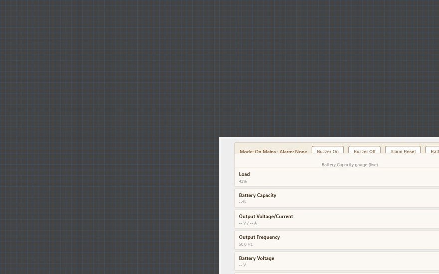
A full-screen page for a Socomec Netys, Itys or Masterys UPS with its mode, alarms, battery and output readings and buzzer and test buttons.
The UPS Panel shows the state of a Socomec UPS and lets the user silence the buzzer, run a battery test and, on Masterys units, reset alarms or switch the UPS off. Its layout is fixed and it reads everything from the UPS Manager. The panel itself has almost no settings.
#When to use it
Use it for a Socomec Netys, Itys or Masterys UPS connected to the gateway over RS232 or RS485 (JBUS/Modbus). If you need to pick which value goes in each field, or show a UPS from another maker, use the UPS Panel (Generic) instead. Put the panel alone on its own page: in the apps it fills the whole screen.
#What you need first
- Modbus device. Open Server > Interfaces > RS232 Interface or RS485 Interface, turn Enabled on and set the serial parameters. Click Configure RTU Devices and add the UPS with the driver Socomec - Socomec UPS JBUS/MODBUS and the UPS's Slave ID. Most Netys, Itys and Masterys units use the RS232 port on the unit. RS485 is only available with the optional Masterys RS485 board. See Modbus devices and datapoints.
- UPS Manager. Open Server > Internal services > UPS Manager and turn Enabled on.
| UPS Manager field | What it does |
|---|---|
| Label | Name of the service in the Configurator. |
| Modbus RTU Device | The UPS you added in step 1. The list shows RS232 and RS485 devices, each with its slave number and port. |
The gateway reads the UPS on a fixed Socomec register map, so no datapoints need to be added by hand.
#Properties
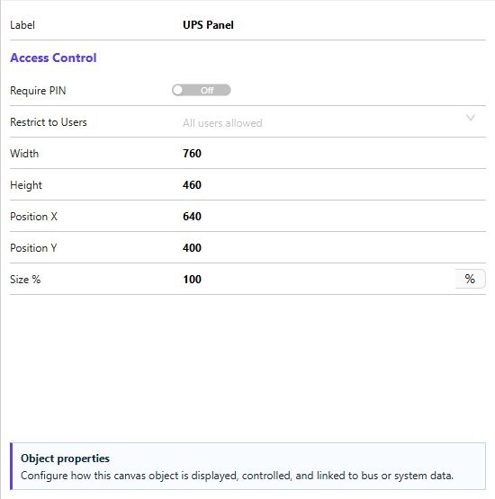
The UPS Panel has only the fields below, described in Common properties. There is no Text Style, Protocol or image field, and there is nothing to map.
| Property | What it does |
|---|---|
| Label | A name for the object in the Configurator. It is not shown in the apps. |
| Require PIN, User access | The Access Control fields. |
| Width, Height | Default 760 by 460. Used only for the preview in the editor. |
| Position X, Position Y, Size % | Editor placement. In the apps the panel fills the screen. |
#How it behaves in the apps
- UPS Controls: a line "Mode: ... Alarm: ...". Mode is On Mains, On Battery or Bypass. Alarm is None, Overload, Input voltage or Alarm active.
- Buttons: Buzzer On, Buzzer Off, Battery Test, Alarm Reset and UPS Off. Buzzer and Battery Test work on all three ranges. Alarm Reset and UPS Off work on Masterys units only, as the panel says. Each command is sent at once and the panel re-reads the UPS afterwards.
- Battery Capacity gauge, 0 to 100 percent.
- Readings: Load (percent), Output Voltage and Current, Output Frequency, Battery Voltage, UPS Temperature, Remaining Backup Time (minutes), Input Mains Voltage and Output Active Power (kW).
- The panel shows single-phase (L1) values only. A value the UPS does not return is shown as
--.
#Example
A Masterys UPS wired to the gateway's RS232 port:
- In RS232 Interface, turn Enabled on, then Configure RTU Devices and add
Main UPSwith the driverSocomec - Socomec UPS JBUS/MODBUSand Slave ID1. Set the baud rate, parity and stop bits to what the UPS uses. - In UPS Manager, Enabled on and Modbus RTU Device
Main UPS (slave 1, RS232). - Add a UPS Panel on a page called
UPSand deploy.
#Tips and common problems
- Everything shows
--: the serial interface is not enabled, the serial settings or Slave ID do not match the UPS, or the UPS Manager has no Modbus RTU Device. - Alarm Reset or UPS Off does not work on a Netys or Itys: those two commands are only supported on Masterys units. Buzzer and Battery Test work on all ranges.
- The UPS has a three-phase output: the panel decodes the L1 values only. For the other phases, use the UPS Panel (Generic) with Modbus datapoints.